
SY120 Starterkit
Functional description
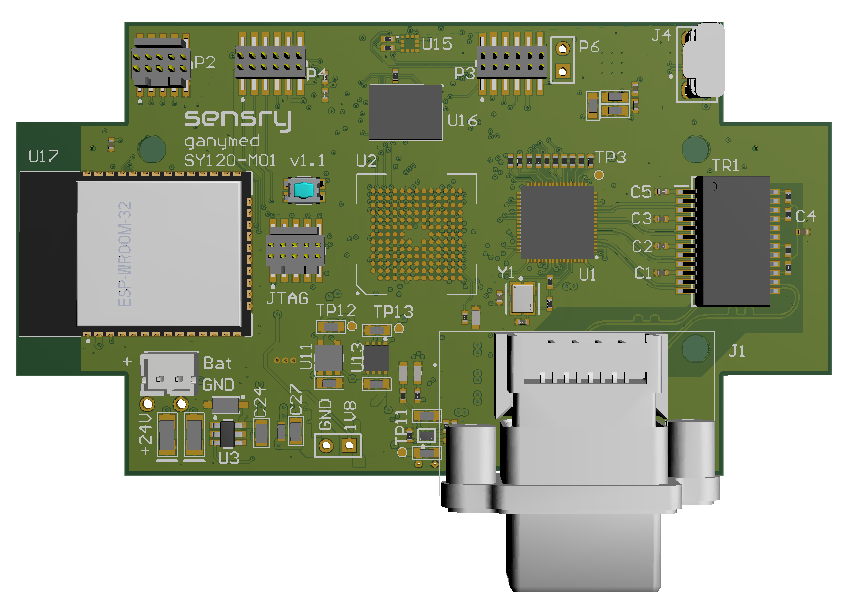
With the SY120 StarterKit it is possible to evaluate the platform in real environment. The StarterKit PCB is equipped with:
- Ganymed SY120-GBM (without top level sensors) or SY120-GEN (with top level sensors)
- S26KS512SDPBHI020 HyperFlash (64MByte NOR-Flash)
- microSD interface (bottom side of the board)
- Ethernet 1000BaseT RJ45 industrial interface
- ESP32-WROOM-23D WiFi 802.11n (2.4GHz) module
- Two TDK ICS-43434 MEMS-Microfones (stereo)
- ST MIS2DH vibration sensor
- Debug interfaces & expansion header
The complete StarterKit system consists of:
- StarterKit PCB
- Binder 4-pin M8-Plug (female) for Power
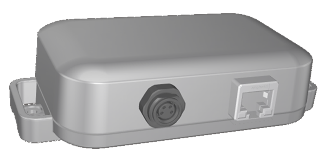
- OKW EasyTec C3206207 case with M8 Power Plug (4-pin) and RJ45 Ethernet Plug
The system can be powered by M8 connector (24V nominal) or direct on the PCB via microUSB.
External Connectors
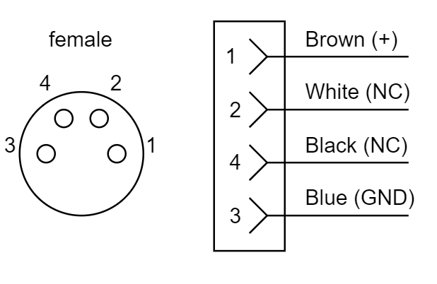
M8 Connector
The M8 4-pin female connector is used to power the sensor.
| Nominal Voltage | 24V |
| Minimum voltage | 12V |
| Maximum voltage | 48V |
| Power | <5W |
The connector has 4 pins. Only 2 Pins are used to to power the device:
Ethernet RJ45 Connector
The RJ45 is a standard industrial 10/100/1000BaseT connector.
PCB description and internal interfaces
Board Scheme Top/Bottom
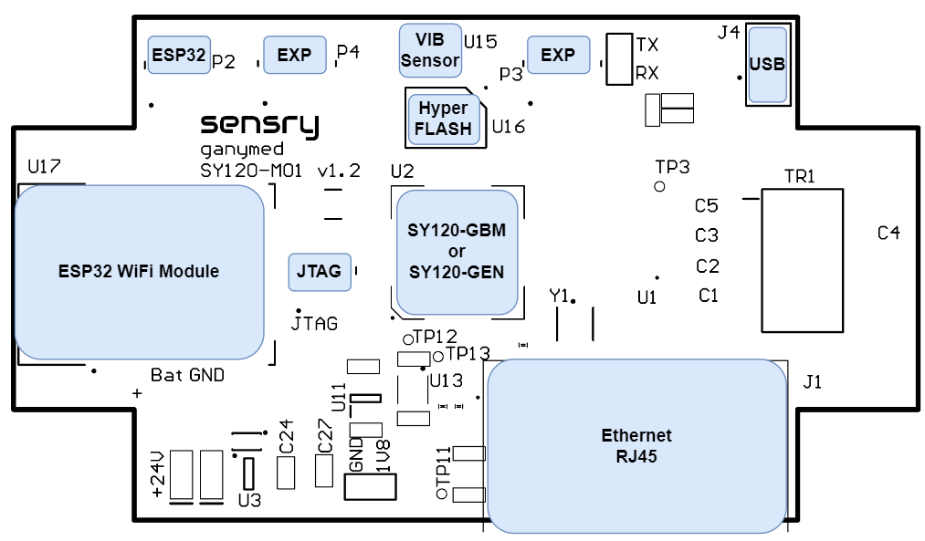
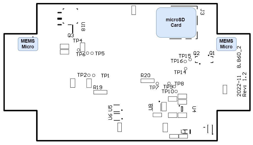
microUSB
The on-board micro USB is used for debugging and powering of the board during development. The USB is connected to UART0 (Kernel Logs) via FTDI Virtual COM Bridge.
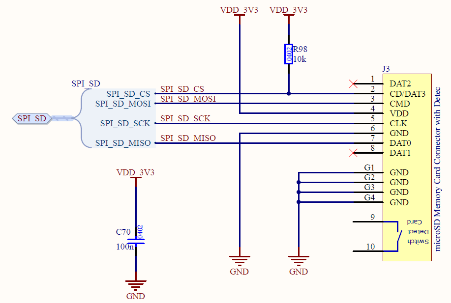
microSD
The microSD card inteface is connected to Ganymed Port SPI5.
JTAG
To use the JTAG interface, following devices are needed:
- Olimex ARM-USB-OCD-H
- SENSRY-JTAG-20-10 adapter
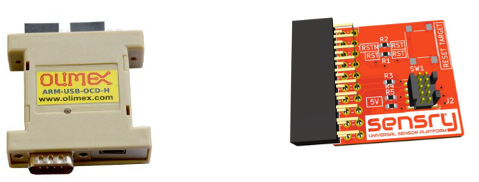
The SENSRY-JTAG-20-10 adapter can be purchased from Sensry. The JTAG port is a 10-pin 1.27mm (0.5”) pin header and fits to the SENSRY-JTAG-20-10 adapter.
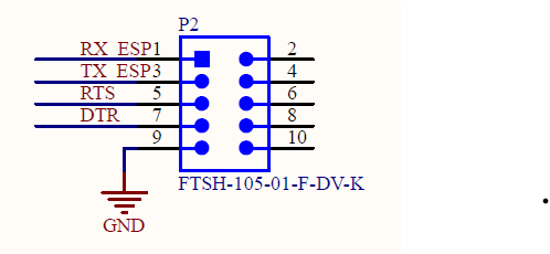
P2 - ESP Prgramming
The port is a 10-pin 1.27mm (0.5”) pin header. The header is used to program the firmware (AT-command set) of the ESP32 if nescessary.
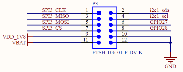
P3 - Extension Header
The port is a 12-pin 1.27mm (0.5”) pin header to use for external sensors and periphery. The voltage level for all ports is 1.8V. It includes one SPI, one I2C and two GPIOs.
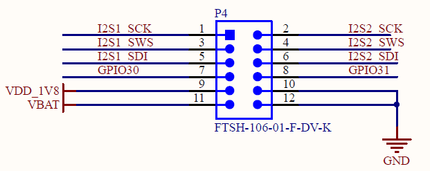
P4 - Extension Header
The port is a 12-pin 1.27mm (0.5”) pin header to use for external sensors and periphery. The voltage level for all ports is 1.8V. It includes two I2S interfaces and two GPIOs.
PCB On-Board Sensors
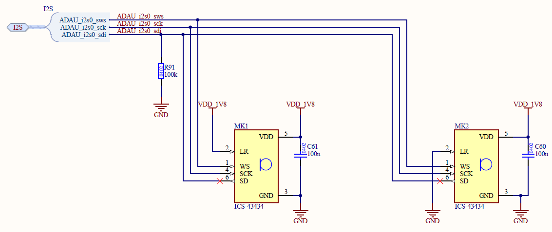
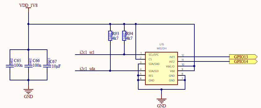
The PCB is equipped with two MEMS microphone sensors and a vibrations sensor.
MEMS-Microphone
The two ICS-43434 are connected as stereo to the I2S Port 0.
Vibration Sensor
The vibration sensor MIS2DH is connected to I2C Port 1. The two interrupt pins are connected to GPIO13 and GPIO14.
Additional On-Board Hardware
LEDs
The board contains a reset switch, a user LED (LED1)connected to GPIO10.
Additionally, there is a power indicator LED for 5V (LED2) and 3.3V (LED3)