SY021-PCB
Overview
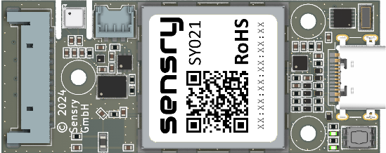
The Kallisto SY021-PCB is a compact sensor module which can be used for application integration as standalone module or assembled on a mezzanine using the Bottom LGA pads. The platform module is delivered with a Zephyr based firmware which makes the system functions accessable over BLE. With the mobile Toolbox App or Python library the moudule can be used instantly to configure sensors and stream sensor data. There are gateway solutions available with partners. Additional functionality is integrated by request and can be purchased from Sensry. Please refer to service@sensry.de for additional information.
The module is equipped with 20 sensors and 4 actuators to support a variaty of applications. Additionally, there is an extension header to add additional sensors or periphery to board.
Features
- LGA Module 55mm x 22mm
- Multiprotocol Bluetooth® Low Energy
- Antenna-on-Module
- Bottom LGA pads for external NFC antenna
- Bottom LGA pads for Qi charge receiver antenna
- Low power ARM microcontroller
- Battery management & LiPo charger
- USB-C for charging
- On-board 128 MByte Flash memory for sensor data logging
- 20 sensor values
- 4 high current low-side driver
Applications
- Industrial IoT & Retrofitting
- Smart Wearable
- Smart Building & Home Automation
- Track & Trace
- Beacons
Integrated Sensors
In its standard configuration, the Kallisto® sensor platform is equipped with a set of rigidly attached sensor components which facilitate the simultaneous detection of 20 different measurands at sampling rates which can be individually configured even after shipment. Optionally, additional sensor components can be connected to the SY021-PCB by making use of its multiple I/O interfaces. The integration in the firmware can be purchased from Sensry GmbH. This flexibility enables a customization according to customer requirements and application needs.
| Measurand | Value Range | Sampling Rate / Hz |
|---|---|---|
| Acceleration | ±4 g ... ±16 g for x-, y-, z-axis | 12.5 ... 800 |
| Angular velocity (Gyrsocope) | ±125 °/s ... ±2000 %/s for x-, y-, z-axis | 25 ... 800 |
| Magnetic Flux | ±50 gauss for x-, y-, z-axis | 10 ... 150 |
| High frequency vibration | ±8 g ...64 g for x-, y-, z-axis | 0.781 ... 25600 Hz |
| Temperature | -40 ... +85 °C | 0.1 ... 1 |
| Relative Humidity | 0 ... 100 %rH | 0.1 ... 1 |
| Ambient Pressure | 300 ... 1100 hPa | 0.1 ... 1 |
| b-VOC (breath-VOC) | 0.5 ... 1000 ppm | 0.017 ... 1 |
| eCO2 (equivalient CO2) | 400 ppm ... infinity | 0.017 ... 1 |
| IAQ (Index Air Quality) | 0 ... 100 | 0.017 ... 1 |
| Light-to-digital | 1.2 ... 10 mW/cm² (for 300 ... 1000 nm wavelength) | 0.1 ... 8 |
| Noise level (audio amplitude) | -135 dbFS ... +3 dBFS (Decibels relative to full scale) | 0.1 ... 1 |
Technical Data
Mechanical Parameters
| Parameter | Value |
|---|---|
| Board Type | LGA with top-side assembly |
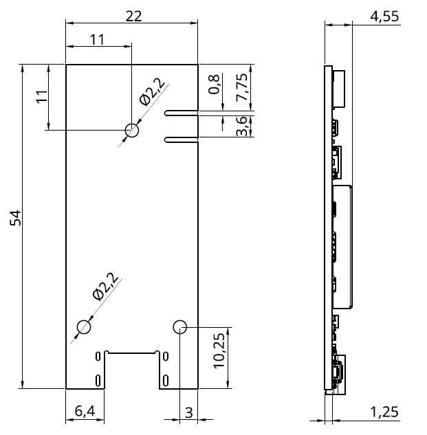
| Size (L x B x H) | 54 mm x 22 mm x 5 mm |
| Mounting holes | 3 x M2 |
| Battery connector | MOLEX 78171-0003 |
| Extension connector | MOLEX 504050-1091 |
| Antenna | on-board chip antenna |
| Power (+ Optional Data) | USB-C |
| Switch Button | Reset |
| LEDs | Charging + BLE connection |
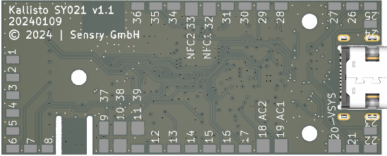
LGA Pinout
The LGA Pinout is for made for mezzanine assembly and future extensions. The following image shows the top view, the LGA pads are on the bottom side of the PCB.
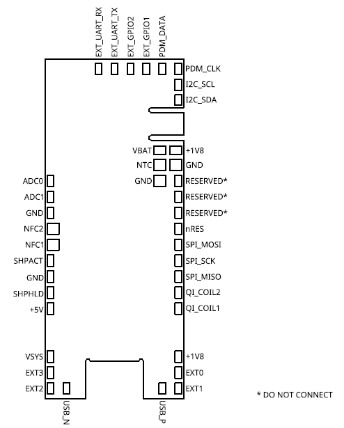
| Pin | Function | Description |
|---|---|---|
| 1 | EXT UART RX | Serial UART RX (same as extension connector) |
| 2 | EXT UART TX | Serial UART TX (same as extension connector) |
| 3 | EXT GPIO 2 | GPIO 2 (same as extension connector) |
| 4 | EXT GPIO 1 | GPIO 1 (same as extension connector) |
| 5 | PDM DATA | PDM DATA (same as extension connector) |
| 6 | PDM CLK | PDM CLK (same as extension connector) |
| 7 | I2C SCL | I2C Clock (same as extension connector) |
| 8 | I2C SDA | I2C Data (same as extension connector) |
| 9 | +1V8 | 1.8V Regulated Power |
| 10 | GND | Ground |
| 11 | RESERVED | Do not connect! |
| 12 | RESERVED | Do not connect! |
| 13 | RESERVED | Do not connect! |
| 14 | nRES | SoC Reset |
| 15 | SPI MOSI | SPI Master Out Slave In |
| 16 | SPI SCK | SPI Clock |
| 17 | SPI MISO | SPI Master In Slave Out |
| 18 | AC 2 | Qi Charge Coil Connector 2 |
| 19 | AC 1 | Qi Charge Coil Connector 1 |
| 20 | +1V8 | 1.8V Regulated Power |
| 21 | EXT 0 | External Low Side Driver 1 |
| 22 | EXT 1 | External Low Side Driver 2 |
| 23 | USB+ | USB Data + |
| 24 | USB- | USB Data - |
| 25 | EXT 2 | External Low Side Driver 3 |
| 26 | EXT 3 | External Low Side Driver 4 |
| 27 | VSYS | System voltage (VUSB or VBAT) |
| 28 | +5V | 5V Board power |
| 29 | SHPHLD | Ship Mode Deactivation |
| 30 | GND | Ground |
| 31 | SHPACT | Ship Mode Activation |
| 32 | NFC 1 | NFC coil connector 1 |
| 33 | NFC 2 | NFC coil connector 2 |
| 34 | GND | Ground |
| 35 | ADC 1 | ADC input 2 |
| 36 | ADC 0 | ADC input 1 |
| 37 | VBAT | Battery voltage (+) |
| 38 | NTC | Battery NTC 10kOhm |
| 39 | GND | Ground |
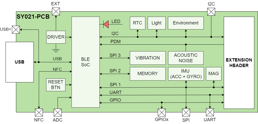
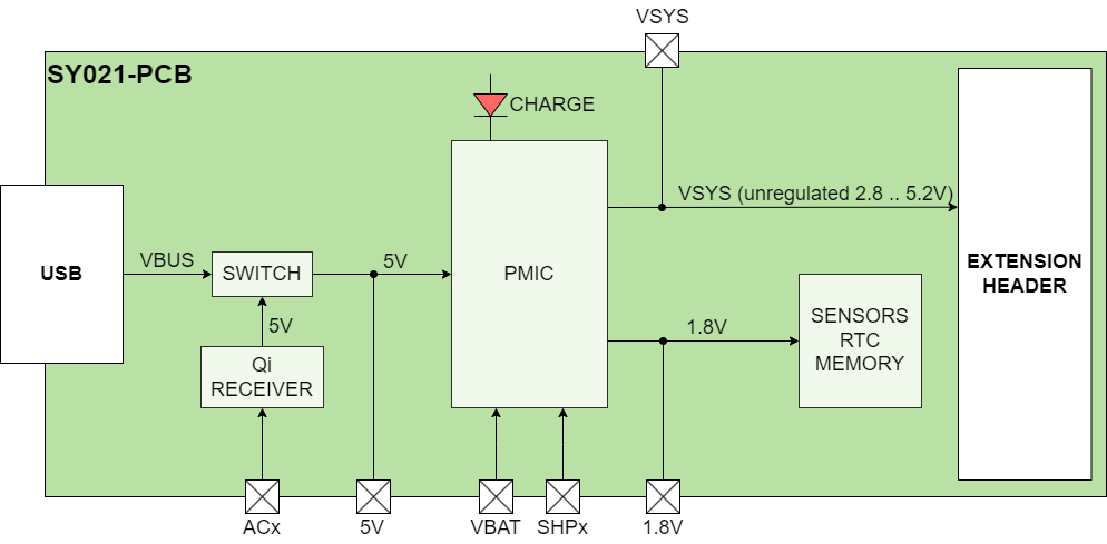
System Schematic
Electrial Parameters
The PCB module can be powered over USB-C, Qi Charger or LiPo-battery. The board system voltage to power the SoC and periphery is 1.8V.
| Parameters | Identifier | Units | Min | Typical | Max |
|---|---|---|---|---|---|
| Battery (LiPo) | VBAT | V | 2.30 | - | 4.35 |
| USB | VBUS | V | 4.1 | 5.0 | 6.7 |
| LGA Pad +5V | +5V | V | 4.1 | 5.0 | 6.7 |
| LGA Pad +1V8 | +1V8 | V | 1.7 | 1.8 | 1.9 |
| System voltage | VSYS | V | 2.8 | - | 5.2 |
| Low-side driver voltage tolerance (4x LGA Pad) | VEXTx | V | 12 | ||
| Low-side driver current tolerance (continious) | IEXTx | A | 2.1 | ||
| LiPo charge current | Ic | mA | 100 | ||
| Quiescent current (in ship mode) | Iq | nA | 460 |
Board Power & Battery Charge
Rechargeable LiPo-batteries can be purchased separately from Sensry. The standard capacities are 150 mAh and 500 mAh, other capacities are available on request. There are several possibilities to power the board:
- USB (w/ or w/o battery)
- LGA pads (+5V, VBAT or 1.8V)
- LiPo battery (on battery connector or LGA pad)
To recharge the battery, the board must be powered either with 5V (USB or 5V LGA pad) or via Qi Charge Coil and a standard Qi charge transmitter.
For wireless charging, a receiver coil must be assembled to the LGA pins AC1 and AC2. The recommendation is a TDK WR222230-26M8-G coil:
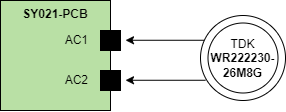
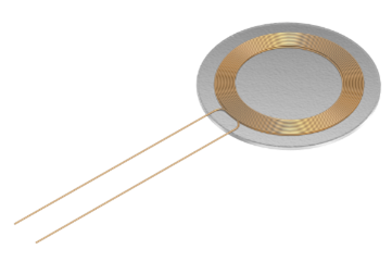
Any standard Qi smartphone charger can be used to charge the module. The receiver coil must be place close (< 1 mm) to the Qi charger.
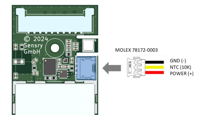
Battery Interface
The LiPo battery must include a 10kOhm NTC.
Extension Interface
The extension interface is equipped with the 10-pin Molex Pico-Lock-Connector 504050-1091 and allows to extend the sensor module with periphery. Molex provide several cable assemblies (MOLEX 15132100x) as a board-to-board connector. The Pinout is described in the following table.
| Pin | Function | Description |
|---|---|---|
| 1 | GND | Ground |
| 2 | VSYS | System voltage |
| 3 | I2C SDA | I²C data interface |
| 4 | I2C SCL | I²C clock interface |
| 5 | PDM CLK | Audio PDM clock interface |
| 6 | PDM DATA | Audio PDM data interface |
| 7 | GPIO 1 | GPIO for future use |
| 8 | GPIO 2 | GPIO for future use |
| 9 | UART TX | Serial UART transmit |
| 10 | UART RX | Serial UART receive |
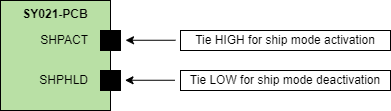
Using The Ship Mode
The ship mode allows to switch off / Shut-down the device completely while the battery is still connected. It isolates the battery and reduces the quiescent current. The ship mode is designed for transportation and long-term storage. Two LGA pads are available to trigger & control the mode externally.
The ship mode can be activated using the SHPACT LGA pin on the bottom side. While the battery is connected and the USB or Qi Power is disconnected (no battery charge), this pin must be tied to HIGH (> 1.1V) for minimum period of 200 ms. Alternatively, the SHPACT pin is connected to an internal Microcontroller pin, so the mode can be activated by firmware.
To deactivate t ship mode, there are two ways: Either connect the USB plug to apply 5V power source or tie SHPHLD LGA pin low (< 0.4 V) for a minimum period of 200 ms.