
SY020-PCB
Overview
Features
- Stamp Module 28.5mm x 15mm
- Multiprotocol Bluetooth® Low Energy
- Antenna-on-Module
- NFC-connector-on-Module
- Wireless Qi Power Receiver
- Low power ARM microcontroller
- Battery fuel gauge
- LiPo charger
Integrated Sensors
- 3-axis Accelerometer
- 3-axis Gyroscope
- 3-axis Magnetometer
- Ambient Temperature
- Relative Humidity
- Air Pressure
- Air Quality
- Light Sensor

Technical Data
| Package dimensions | High density PCB 28.5mm x 15mm(L x W) |
| Supply Voltage | 2.2V…5.5V (compatible with Li-Ion, Li-SOCl, Li-MnO2 and 2 Alkaline batteries) Internal Step-down converter for 1.8V Up to 90% efficiency at 10μA |
| Digital Interfaces | I2C, SPI, UART, GPIOs |
| Analog Interfaces | 12-Bit SAR ADC (3 inputs, 14-bit with oversampling) |
| Special Interfaces | NFC coil, Charge coil, 4 low-side driveroutputs |
| MCU | 32bit ARM Cortex M4F–Nordic nRF52840 1MB Flash memory, 256kB RAM OTA (over the air) firmware update |
| 3-axis Accelerometer (Bosch BMI160) | Acc. ranges: ±2g, ± 4g, ±8g, ±16g ±2g: 16384 LSB/g ±4g: 8192 LSB/g ±8g: 4096 LSB/g ±16g: 2048 LSB/g |
| 3-axis Gyroscope (Bosch BMI160) | Gyro. ranges: ± 125°/s, ± 250°/s, ± 500°/s, ± 1000°/s, ± 2000°/s Gyro. typical sensitivity:±125 °/s: 262.4 LSB/°/s ±250 °/s: 131.2 LSB/°/s ±500 °/s: 65.6 LSB/°/s ±1000 °/s: 32.8 LSB/°/s ±2000 °/s: 16.4 LSB/°/s |
| 3-axis Magnetometer (Bosch BMM150) | EMF ranges: ± 1300 μT (x-, y-axis); ± 2500 μT (z-axis) Resolution:0.3 μT – 12 Bit |
| Temperature (Bosch BME680) | -40 … 85°C Accuracy: 0 … 64°C: ±1.0°C -20 … 0°C: ±1.25°C -30 … -20°C: ±1.5°C |
| Relative Humidity (Bosch BME680) | 0 … 100% rel. humidity Response time: 8s Accuracy tolerance:±3% rel. humidity Hysteresis:≤1% rel. humidity |
| Pressure (Bosch BME680) | Pressure Range: 300 … 1100 hPa RMS Noise:0.2 Pa, equiv. to 1.7cm Offset temp. coeff.:±1.5 Pa/K |
| eqCO2 (Bosch BME680) | Estimation of CO2level in ppm |
| b-VOC (Bosch BME680) | Estimation of breath-VOC equivalents in ppm |
| Air quality (Bosch BME680) | Air Qualitiy Index:direct output of IAQ: Index for Air Quality |
| Light Overview (TI OPT3002) | Optical Spectrum: 300nm – 1000nm Measurement levels:1.2nW/cm² - 10mW/cm² |
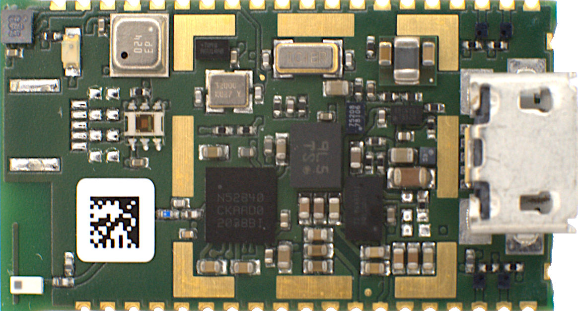
Frontside Board Layout

| BLE | BLE Antenna |
| NFC | NFC-Connector |
| M | Magnetometer |
| LED | System LED |
| E | Environment Sensor (Temperature, Humidity, Air Pressure, Air Quality) |
| IMU | Inertial Measurement Unit (Acceleration, Gyroscope) |
| D | Low-Side Driver |
| USB | USB-Connector |
| Shield | EMV Shielding |
Pin Description
SWD
| Function | Description | SY020-PCB Pin | nRF52840 |
|---|---|---|---|
| SWCLK | Single Wire Debug Clock | 1 | SWDCLK |
| SWDIO | Single Wire Debug Data | 2 | SWDIO |
The SWD port can be used to program and debug the board using an JTAG debugger (like Segger J-Link). For further descriptions please refer to the Nordic nRF52840 product specification.
Charge Coil
| Function | Description | SY020-PCB Pin |
|---|---|---|
| AC1 | Coil connector 1 | 12 |
| AC2 | Coil connector 2 | 13 |
The charge coil pins can be used to add a charge coil for Wireless Qi Charge. The fitting charge coil can be delivered as add-on to the board.
SPI Master
| Function | Description | SY020-PCB Pin | nRF52840 |
|---|---|---|---|
| MISO | Master In / Slave Out | 41 | P1.09 |
| MOSI | Master Out / Slave In | 39 | P0.08 |
| SCK | SPI Clock | 40 | P0.05 |
Any GPIO can be programmed as Chip Select for the Slave device. The voltage level on the all SPI ports is 1.8V. For further descriptions please refer to the Nordic nRF52840 product specification chapter 6.24.
I2C Master
| Function | Description | SY020-PCB Pin | nRF52840 |
|---|---|---|---|
| SDA | Serial Data | 37 | P1.10 |
| SCL | Serial Clock | 36 | P1.14 |
The port has internal Pull-Ups to 1.8V. For further descriptions please refer to the Nordic nRF52840 product specification chapter 6.29.
GPIO
The General Purpose IOs can be individually programmed as inputs / outputs. The I/O voltage level is 1.8V. For further descriptions please refer to the Nordic nRF52840 product specification.
| Function | Description | SY020-PCB Pin | nRF52840 |
|---|---|---|---|
| GPIO0 | General purpose input / output 1 | 3 | P0.25 |
| GPIO1 | General purpose input / output 2 | 4 | P1.00 |
| GPIO2 | General purpose input / output 3 | 5 | P0.22 |
| GPIO3 | General purpose input / output 4 | 6 | P0.24 |
| GPIO4 | General purpose input / output 5 | 7 | P0.19 |
| GPIO5 | General purpose input / output 6 | 8 | P0.20 |
| GPIO6 | General purpose input / output 7 | 9 | P0.21 |
| GPIO7 | General purpose input / output 8 | 10 | P0.23 |
| GPIO8 | General purpose input / output 9 | 15 | P0.16 |
| GPIO9 | General purpose input / output 10 | 16 | P0.13 |
| GPI10 | General purpose input / output 11 | 25 | P0.17 |
| GPI11 | General purpose input / output 12 | 26 | P0.14 |
| GPI12 | General purpose input / output 13 | 32 | P0.26 |
Analog Inputs
| Function | Description | SY020-PCB Pin | nRF52840 |
|---|---|---|---|
| ADC0 | Analog input 1 | 33 | P0.28 / AIN4 |
| ADC1 | Analog input 2 | 34 | P0.30 / AIN6 |
| ADC2 | Analog input 3 | 35 | P0.02 / AIN0 |
The analog inputs can be used to convert analog voltages up to 1.8V to digital. This port can be used additionally as GPIO. For further descriptions please refer to the Nordic nRF52840 product specification chapter 6.23.
Low Side Driver
| Function | Description | SY020-PCB Pin | nRF52840 |
|---|---|---|---|
| EXT0 | Low side driver 1 | 17 | P0.18 |
| EXT1 | Low side driver 2 | 18 | P0.15 |
| EXT2 | Low side driver 3 | 23 | P0.06 |
| EXT3 | Low side driver 4 | 24 | P0.27 |
The ports are open drain low sider driver. The TI CSD13380F3 MOSFET is able drive loads up to 2.1A continuous and 13.5A pulsed (pulse duration < 100µs, duty cycle < 1%). The maximum drive voltage is 12V.

USB
For using the platform as a part of a system without assembled USB connector, The USB Pins can be used to connect an external USB connector .
| Function | Description | SY020-PCB Pin | nRF52840 |
|---|---|---|---|
| USB_N | USB - | 20 | D - |
| USB_P | USB + | 21 | D + |
| SCK | USB_5V | 29 | - |
Power
| Function | Description | Power | SY020-PCB Pin |
|---|---|---|---|
| VDD_CORE | Core Power | 1.8V, max. 200 mA total | 27 |
| VDD_EXT | External Power | 1.8V, max. 200 mA total | 31 |
| VBAT | LiPo Battery + | 3.0 … 4.2 V | 30 |
| USB_5V | USB Bus Power | 5V, max. 500mA | 29 |
| GND | Ground level | 11, 14, 19, 22, 28, 38 |
The Board Power is 1.8V with a maximum driving current of 200 mA (VDD_CORE + VDD_EXT). The VDD_CORE 1.8V power rail is used to power components which should be always on (also in idle/advertisement modes). The VDD_EXT 1.8V power rail is used to power external peripheral components which should be only on in an active state. The VDD_EXT can be enabled internal by a nRF52840 GPIO (VDD_CTRL).
The battery port can be used to connect a re-chargeable Lithium Polymer single cell (3.7V) battery. The charge current is 50mA by default.
Internal Pin Description
The pins of the Nordic nRF52840 are mapped regarding the following table:
| Function | nRF52840 Pin | Device function |
|---|---|---|
| SYS_LED | P1.12 | System LED on/off |
| BMI_CSB | P0.12 | BMI160 Chip select |
| BMI_INT1 | P1.11 | BMI160 Interrupt 1 |
| BMI_INT2 | P0.07 | BMI160 Interrupt 2 |
| BMM_CSB | P1.01 | BMM150 Chip Select |
| BMM_INT | P1.04 | BMM150 interrupt |
| BMM_DRDY | P1.03 | BMM150 Data ready |
| BME_CSB | P1.15 | BME680 Chip select |
| OPT_INT | P1.06 | Optical sensor interrupt |
| VDD_CTRL | P1.08 | VDD_EXT enable/disable |
| BMS2_ALERT | P1.13 | Battery Gauge interrupt |
| CHRG_INT | P0.04 | Charge voltage sense |
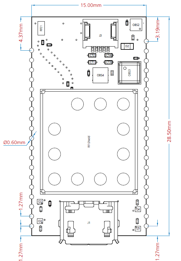
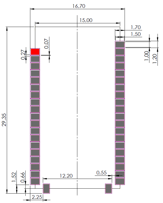
PCB Dimensions & Footprint
Platform Nomenklatura and Order Variants
| Wireless I/F | LiPo Battery Charge | Sensors / Actuators | |||||||||||||||||||||||
| SY020-PCB |
|
|
|
| NO CHARGE | WIRELESS QI CHARGE | WIRELESS QI + USB CHARGE | |
| BLE | SY020-PCB-B-x-IM | SY020-PCB-B-W-IM | SY020-PCB-B-WU-IM |
| BLE | SY020-PCB-B-x-L | SY020-PCB-B-W-L | SY020-PCB-B-WU-L |
| BLE | SY020-PCB-B-x-EA | SY020-PCB-B-W-EA | SY020-PCB-B-WU-EA |
| BLE | SY020-PCB-B-x-IMEA | SY020-PCB-B-W-IMEA | SY020-PCB-B-WU-IMEA |
| BLE | SY020-PCB-B-x-IML | SY020-PCB-B-W-IML | SY020-PCB-B-WU-IML |
| BLE | SY020-PCB-B-x-IMD | SY020-PCB-B-W-IMD | SY020-PCB-B-WU-IMD |
| BLE | SY020-PCB-B-x-IMEAL | SY020-PCB-B-W-IMEAL | SY020-PCB-B-WU-IMEAL |
| BLE | SY020-PCB-B-x-IMEAD | SY020-PCB-B-W-IMEAD | SY020-PCB-B-WU-IMEAD |
| BLE | SY020-PCB-B-x-IMEALD | SY020-PCB-B-W-IMEALD | SY020-PCB-B-WU-IMEALD |