SY120 Starterkit Datasheet
Overview
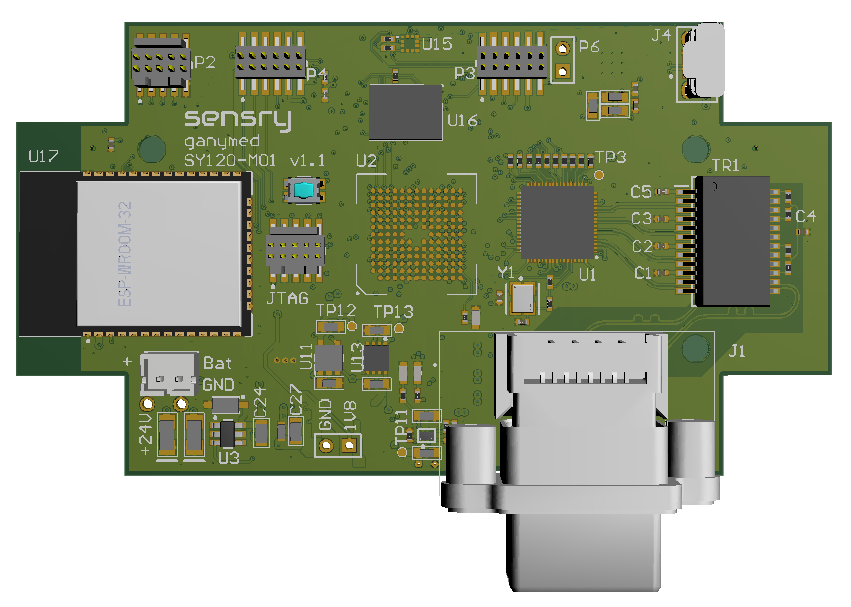
With the SY120 StarterKit it is possible to evaluate the platform in real environment. The StarterKit PCB is equipped with:
- Ganymed SY120-GBM (without top level sensors) or SY120-GEN (with top level sensors)
- microSD interface (bottom side of the board)
- Ethernet 1000BaseT RJ45 industrial interface
- ESP32-WROOM-23D WiFi 802.11n (2.4GHz) module
- Two TDK ICS-43434 MEMS-Microfones (stereo) on PCB
- ST MIS2DH vibration sensor on PCB
- Debug interfaces & expansion header
The complete StarterKit system consists of:
- StarterKit PCB
- Binder 4-pin M8-Plug (female) for Power
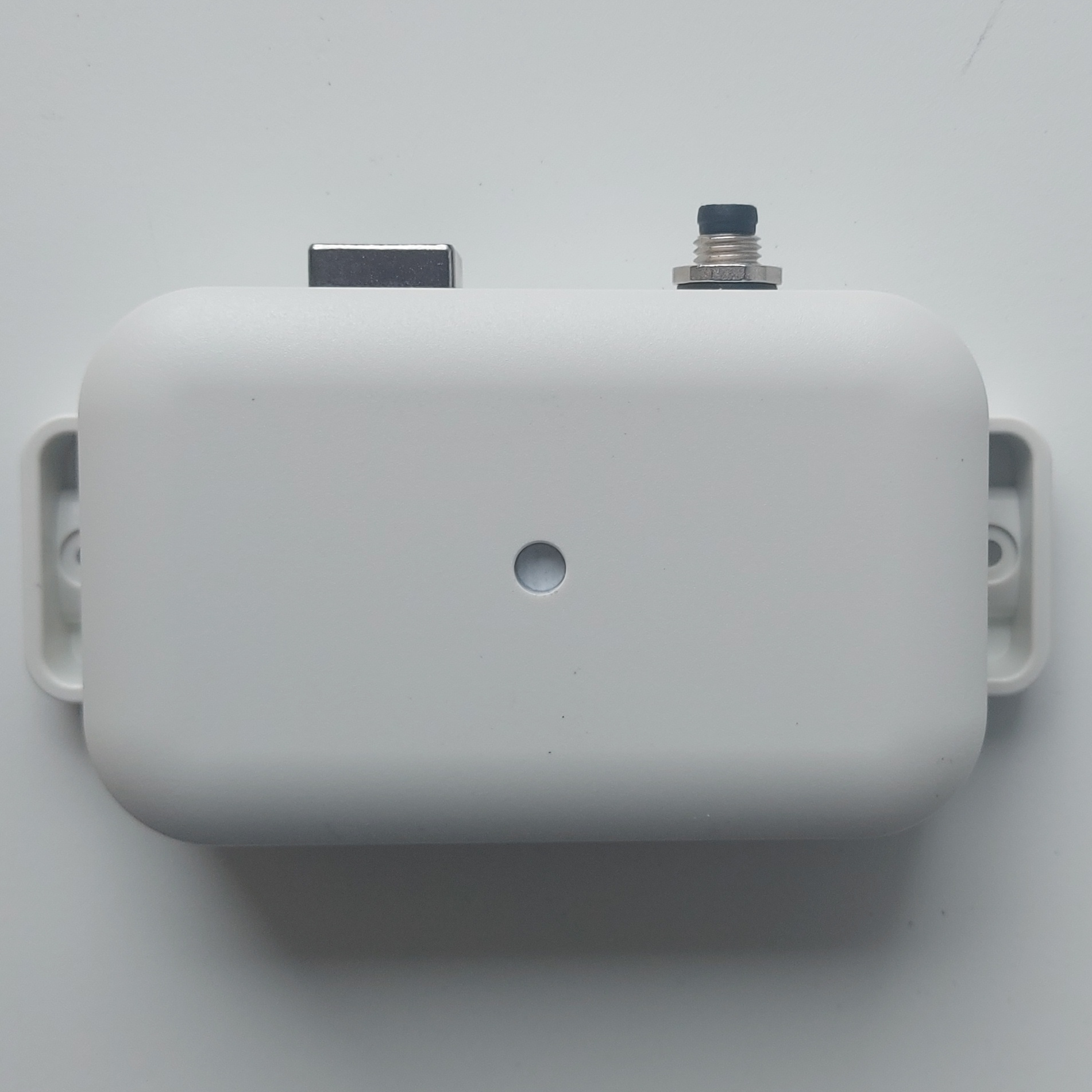
- OKW EasyTec C3206207 case with M8 Power Plug (4-pin) and RJ45 Ethernet Plug
- The system can be powered by M8 connector (24V nominal) or direct on the PCB via microUSB.
External Connectors
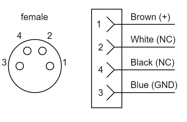
Power
The M8 4-pin female connector is used to power the sensor.
| Parameter | Min | Nominal | Max |
|---|---|---|---|
| Supply Voltage | 12 V | 24 V | 48 V |
| Power dissipation | 5 W |
The connector has 4 pins. Only 2 Pins are used to to power the device:
Ethernet
The Ethernet interface is a standard industrial RJ45 10/100/1000BaseT connector.
Internal PCB Interface
microUSB
The on-board micro USB is used for debugging and providing board power during development. The USB is connected to UART0 (Kernel Logs) via FTDI Virtual COM Bridge.
microSD
The microSD card inteface is connected to Ganymed Port SPI5.
JTAG
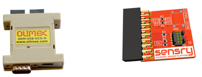
To use the JTAG interface, following devices are needed:
- Olimex ARM-USB-OCD-H
- SENSRY-JTAG-20-10 Adapter
- 5x2-Pin 1.27 mm - Pitch Ribbon Cable Connector
Additional On-Board Hardware
The board contains a reset switch, a user LED (LED1)connected to GPIO10. Additionally, there is a power indicator LED for 5V (LED2) and 3.3V (LED3)
For further questions, development, and programming support, and for access to our dedicated Gitlab repository, please contact our support via support@sensry.de.