SY120 Breakout Board Datasheet
Overview
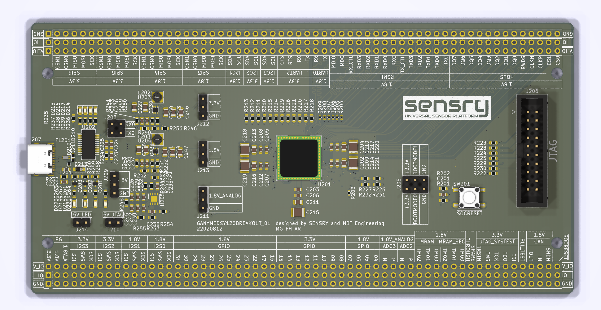
With the SY120 Breakout Board it is possible to evaluate the platform in and get access to all SoC interfaces. The Breakout Board PCB is equipped with:
- Ganymed SY120-GBM (without top level sensors) or SY120-GEN (with top level sensors)
- USB-C interface (Power & Data)
- Debug interface
- Expansion header
Hardware
Power
The Board cna be powerd via: * USB-C Interface * JTAG-Interface * From external 5V source
USB interface
The USB-C is connected via USB-Serial connector to the UART0 interface of the Ganymed SoC.
BOOTMODE Jumper
The boot mode can be configured via J205.
| BOOTMODE0 | BOOTMODE1 | Mode | Description |
|---|---|---|---|
| 0 | 0 | MRAM | The bootloader loads the image from the non-volatile secure MRAM to the secure SRAM. |
| 1 | 0 | UART | The bootloader blocks in a UART mode. It is possible to limages via UART0 to the SRAM or to the MRAM. |
| 0 | 1 | JTAG | The bootloader is blocked in ja JTAG-Loader mode. It is possible to load images via UART0 to the SRAM or to the MRAM |
| 1 | 1 | Reserved | - |
External Connectors
The external connector assignmend is printed in the silk screen of the PCB.
JTAG
To use the JTAG interface, following devices are needed:

Additional On-Board Hardware
The board contains a reset button. The Power Status LEDs can be disabled by open jumper J214.
Software development
The board and Ganymed SoC are supported by Zepyhr RTOS. Please refer to the the Zephyr Getting Started documentation to start with the board.